Jansen Leg Analysis
UIUC's junior-level design course (ME 370: Mechanical Design I) spends the semester learning about and applying concepts related to planar kinematics, machine dynamics, and structural design. Due to complications of the COVID-19 pandemic during the Spring 2020 term, the final stages of ME 370’s semester-long design project were replaced with a virtual analysis of an intricate, kinematic mechanism.
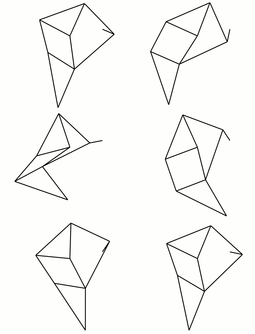
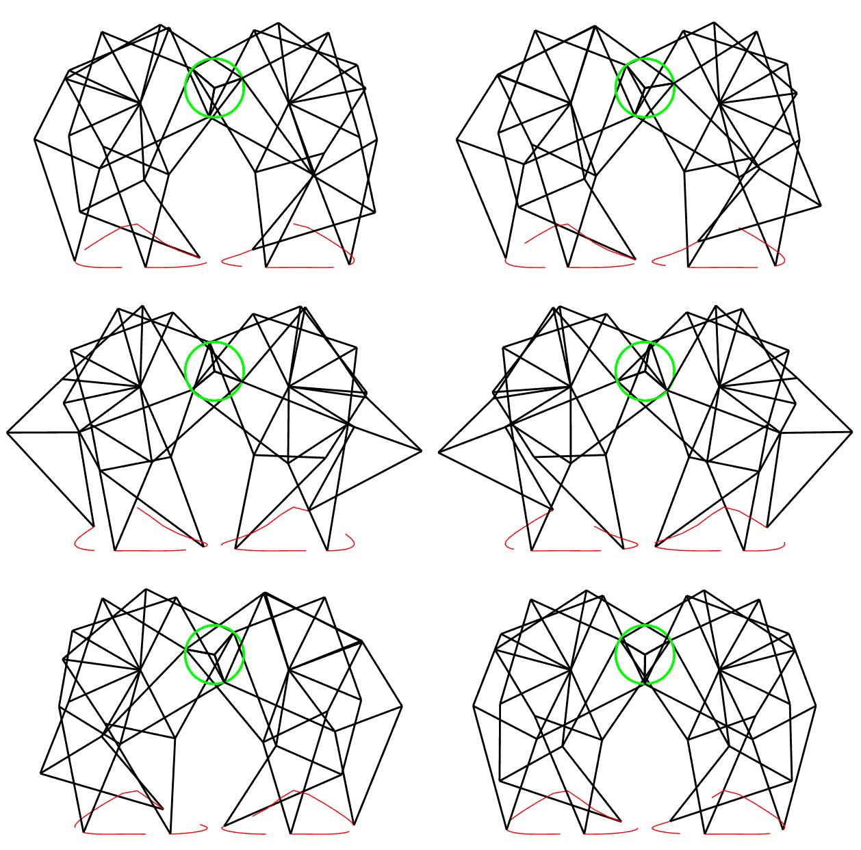
Many variations of mechanical walkers (or legged robots) exist, including 2-legged (humanoid), 4-legged (quadrupeds), 6-legged (hexapod) and 8-legged (octopod) walkers. For our virtual analysis, we investigated a 6-legged walker known as a Strandbeest, focusing on the individual Jansen’s Linkage making up each leg on our walker. Various stages of the investigation included PVA (position, velocity, and acceleration) analysis and DFA (dynamic force analysis) for the individual leg mechanism in the form of hand calculations and computational analysis with MATLAB. This analysis came together for a final analysis of the walking robot’s movement and velocity.
Part 1: Hand Calculations of PVA & DFA of a Single Leg Mechanism
The first portion of this project pertained to the symbolic PVA (position, velocity, and acceleration) analysis and DFA (dynamic force analysis) of the Jansen leg mechanism. This analysis served to understand the motion and forces at the point P of the Jansen Leg which would come in contact with the ground. From the known link lengths, geometry, and input motion of the crank, the output motion of the point P was symbolically derived.
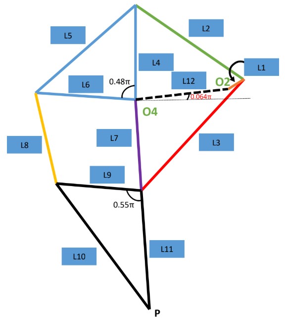
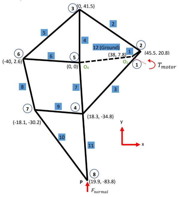
Part 2: Computational Analysis with PVA & DFA of a Single Leg Mechanism
Using the theoretical formulas derived in Part 1, a MATLAB script was created and modified to numerically perform PVA analysis and DFA on the mechanism. The results from this numerical investigation provided values and diagrams displaying the actual motion of the mechanism. These results would be used for further analysis in Part 3 to estimate the forward velocity of the robot given its inputs.
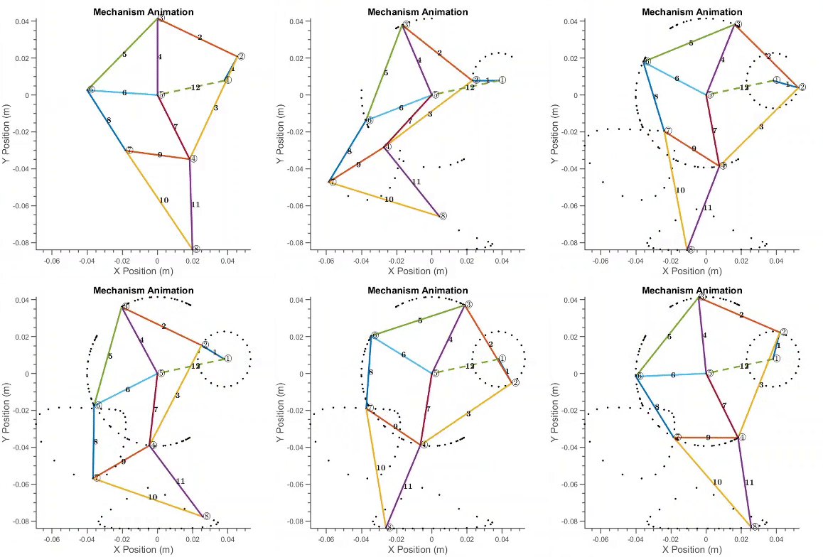
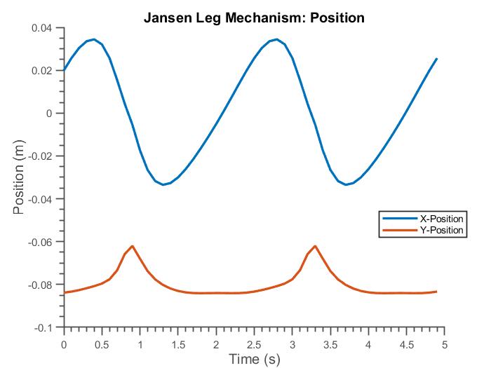
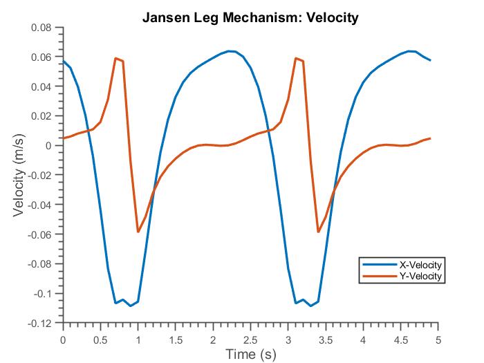
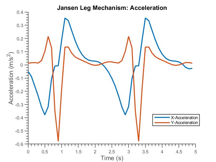
Part 3: Evaluation of Walking Robot Velocity
The results from the investigations performed in Parts 1 and 2 were used to relate the Strandbeest’s velocity to the input crank. Concepts such as instantaneous centers, locations of maximum torque, and motor functionality requirements (torque vs. angular velocity) were applied. Several relationships were formed based on the following knowledge and assumptions of the mechanism:
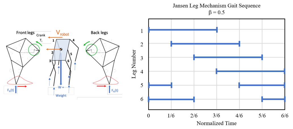
- Gait and Leg Coordination: The Strandbeest is designed so the 6 legs are broken up into 3 pairs. All legs are driven off a single drive shaft, and the robot has a gait where 3 legs touch the ground at any given moment. Each pair of legs face in opposite directions leading them to be 180 degrees out of phase. The crank shafts of each pair are set 120 degrees off from one another, so each pair of legs is 120 degrees out of phase.
- Weight and Force Distribution: The weight of the Strandbeest is distributed amongst all the legs in contact with the ground at any given moment. Which and how many feet are in contact with ground at any given moment changes through the gait. Each foot in contact with the ground has a normal force acting on it.
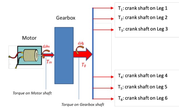
- Motor and Power Flow: The Strandbeest’s motor is connected through a gearbox to the drive shaft powering all legs. Because the speed of the motor is very different from the speed of the legs, a gearbox is needed to transmit and increase/reduce the torque/speed from the motor to each crankshaft.
